|
OpenWRT Smart 7688 IoT board |
Description
OpenWRT Smart 7688 IoT is an open development board based on MT7688(datasheet).
The board is based on the OpenWrt Linux distribution.
The board is designed especially to enable prototyping of Rich Application IoT devices for smart home or office.
The board offers you the memory and packet storage to enable robust video processing.
The platform also offers options to create device applications in Python, Node.js and C programming languages.
Specifications
| Operating Temperature (CPU): | -40°C ~ +85°C |
| Power: | USB Powered |
| Connection to PC: | USB Virtual COM port |
| Virtual COM Port Device Drivers: | Windows 8 / 7 / Vista / Server 2003 / XP / 2000Mac OS-X / OS-9Linux |
| MPU: | Chipset: MT7688AN Core: MIPS24KEc Clock Speed: 580MHz Working Voltage: 3.3V |
| Memory: | Flash: 32MB RAM: 128MB DDR2 |
| UART Lite: | Pin Number: P8/P9 |
| USB Host: | Connector Type: USB 2.0 Mirco Type B Plug |
| Communication: | Wi-Fi: 1T1R 802.11 b/g/n (2.4G) Ethernet: 1-port 10/100 FE PHY |
Features
- USB 2.0 Mirco Type B Plug.
- 580 MHz MIPS CPU.
- Single input single output(1T1R) Wi-Fi 802.11 b/g/n (2.4G).
- Pin-out for GPIO, UART and Ethernet Port
- 32MB Flash and 128MB DDR2 RAM
- USB host & USB device
- Micro SD slot
- Provide optional connection golden finger for connect other device without soldering.
- Provide extra 3V USB power source for other device, Do not worry to find extra power source.
- build-in reset button and Wifi button.
- OpenWRT compatible.
- Python, Node.js and C programming languages
- Support file share(samba), putty and Termite tools.
- Using Silicon Lib as Virtual COM port Device dirver.
Application ideas
- IoT/Gateway Device.
- Robotics.
- Teaching and learning.
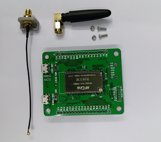
Package Content:
- OpenWRT Smart7688 IoT
- Silicon labs CP2102 usb to uart bridge (built-in 5V to 3.3V Low dropout power regulator.)
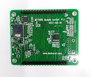
- MT7688 broad
- Master broad with golden finger
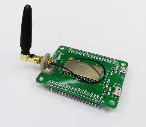
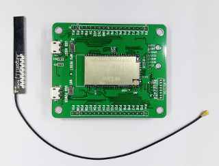
External Antenna package set
- Antenna socket holder
- Antenna cable
- External Antenna
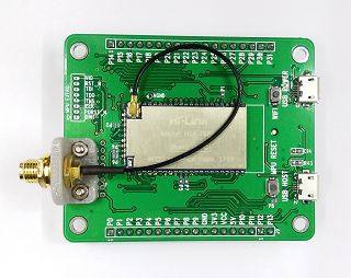
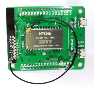
Internal Antenna package set
- PCB Antenna with cable
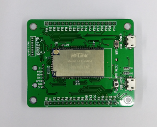
Without Antenna package set
Shipping and Payment:
- Accept PayPal Only
- Worldwide shipping via Airmail
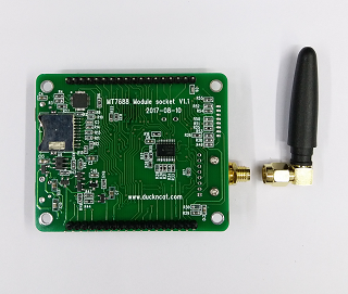
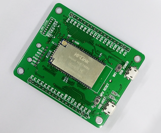
Build-in MT7688 broad
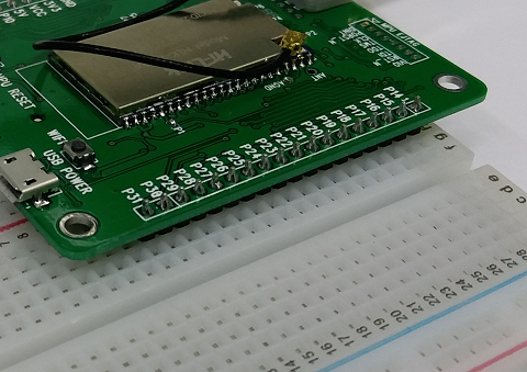
Solderless Breadboard support
Broad size
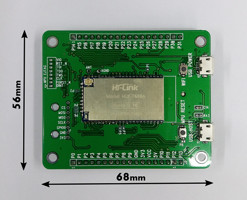
Broad Pin labels

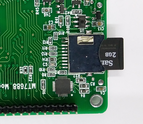
Buld-in SD Card Slot
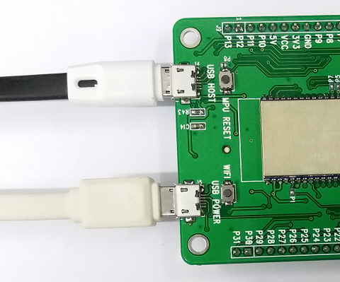
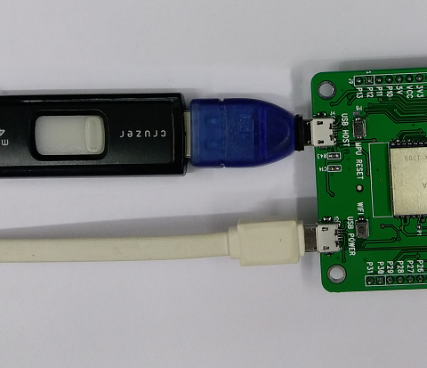
Two USB Slots connection
- USB Host connect to device units
- USB Power connect to PC for UARTs
- USB Host connect to mass storage
- USB Power connect to PC for UARTs
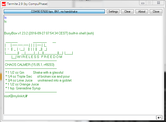
Use termite
After connect to PC, you may run UART communication tools eg: termite.
Serial port setting:
Baud rate 57600
Data bit 8 , Stop bits 1 , parity none
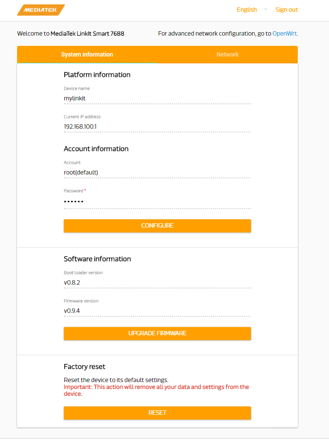
Connect to the Web UI
LinkIt Smart 7688 Web UI allows you to configure system information, upgrade firmware, perform device reset and change between Wi-Fi AP and Station mode and more. The following steps apply to Windows, Mac OS X and Linux.
1) Power on Module development board by using any USB power source, for example your computer and a micro USB cable.
Make sure you connect the cable to the Power (PWR) connector, not the USB host (HOST) connector near the MPU reset button. The green ON LED (Power on) will light up solid first, followed by a blink from the orange Wi-Fi LED (bootloader initialization). Then, after about 5 seconds, the device boot up starts.
After boot up, the Wi-Fi LED turns off. This means the system is ready to accept Wi-Fi connection and the steps are described next.
2) Open the Wi-Fi connection utility on your computer and connect to the access point named LinkIt_Smart_7688_1B09F3 (1B09F3is the MAC address and yours could be different).
After you have connected to LinkIt_Smart_7688_XXXXXX AP, the Wi-Fi LED will blink three times per second.
Keep in mind that once you have connected to Smart7688IoT, your computer may no longer have access to the internet - it is now joined the Local Area Network formed by Smart7688IoT.
Default SSID: LinkIt_Smart_7688_XXXXXX
mDNS Hostname: mylinkit.local
IP: 192.168.100.1
3) In your web browser open http://mylinkit.local
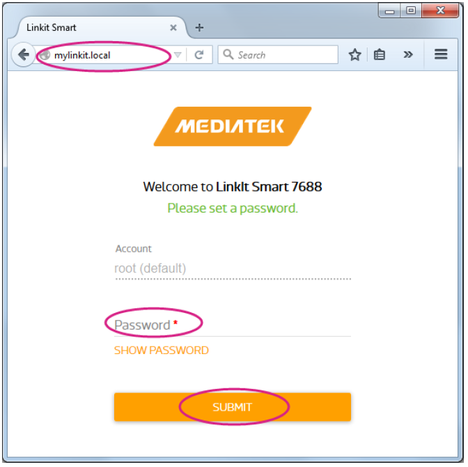
4) Click on the Password field and set a password using at least 6 alphanumeric characters. Click Submit and enter the password again to Sign In.
Reset or network Re-configuration.
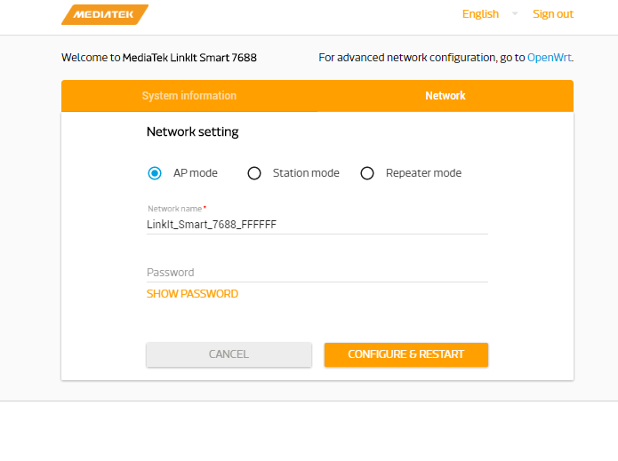
Config to Access Point Mode (AP mode)
In AP mode a Smart7688 IoT development board forms a LAN and acts as an access point. AP mode is used mainly to configure the board settings.
Default SSID: LinkIt_Smart_7688_XXXXXX
mDNS Hostname: mylinkit.local
IP: 192.168.100.1
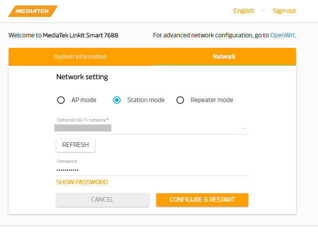
Config to Station Mode in Network setting.
In Station mode a LinkIt Smart 7688 development board is able to access the Internet by joining a Wi-Fi network.
mDNS Hostname: mylinkit.local
IP: Assigned by Wi-Fi AP
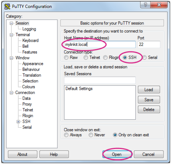
Use PuTTY
- 1) Install PuTTY from here.
- 2) Type mylinkit.local in the Host Name box, check the SSH radio button and click Open as shown
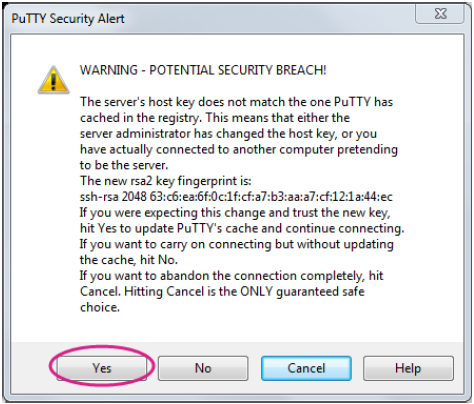
- 3) A Security Alert window will pop up as shown in Figure 20 below, this happens when you use PuTTY for the first time, or after upgrading firmware, or use a different board. Click Yes.
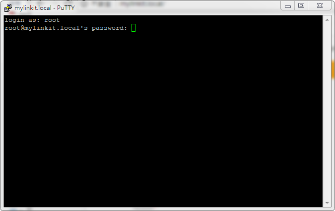
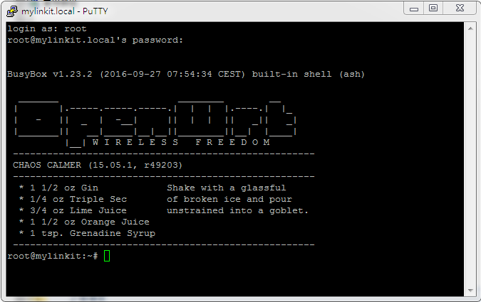
- 4) In the PuTTY terminal window that opens, log in with username root and enter the password you set previously in the Web UI, after log in you should see a screen similar to
For Mac:
Open Terminal. In the Terminal, type ssh root@mylinkit.local at the command line, hit return and you'll be prompted to enter the root password. Enter the password you set previously in the Web UI.For Linux:
Open Terminal. In the Terminal, type ssh root@mylinkit.local at the command line, hit return and log in using the password you set previouslyConnection information
Host name: mylinkit.local
Port: 22
Connection type: SSH
Login User name root
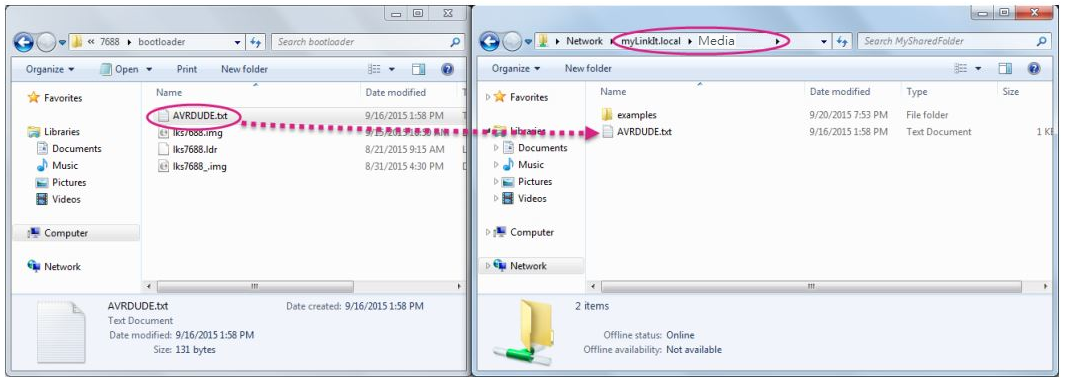
Enable samba for (Read / Write)
Open Termite and type chmod 777 /Media
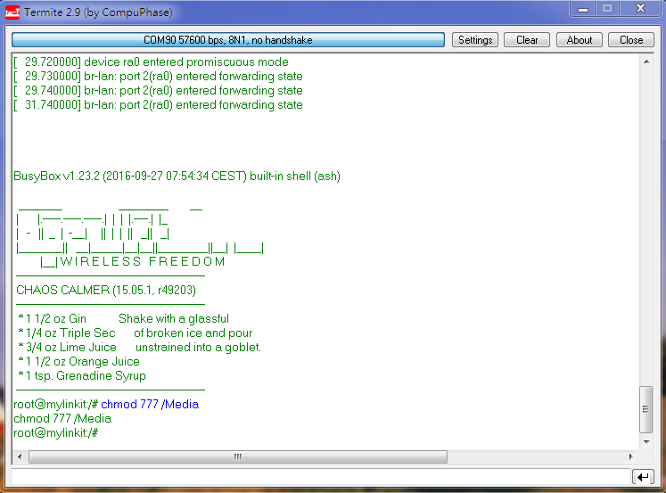
Open file explorer and type \\mylinkit.local, you should see the Media folder. Open another file explorer, drag and drop your file to Media folder, show below.
Use Python and mraa control GPIO interface
Create new Python code
(example code is flash LED)
1. Use vim editor
vim blink.py
2. write python code and save.
import mraa
import time
# Refer to the pinout digram for the GPIO number to silk print mapping # in this example the number 44 maps to Wi-Fi LED.
pin = mraa.Gpio(44)
pin.dir(mraa.DIR_OUT)
while True:
   pin.write(1)
   time.sleep(1)
   pin.write(0)
   time.sleep(1)
3. Run python code.
python ./blink.py
Use Node.js and mraa control GPIO interface
Create new javaScript code
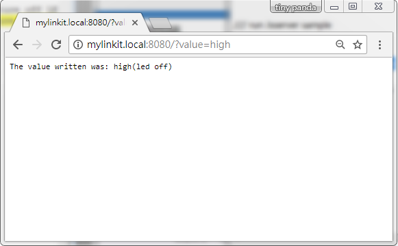
This example code is through Web Server control GPIO to flash LED
Type http://mylinkit.local:8080/?value=high in Web browser to ture off LED
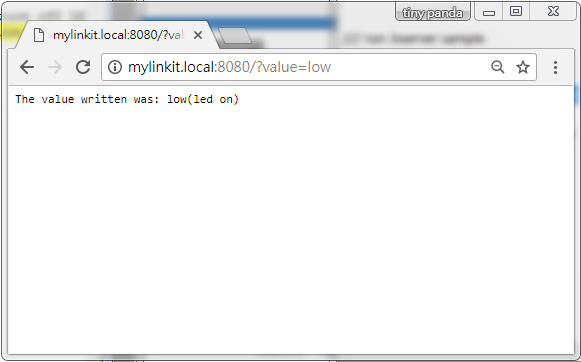
Type http://mylinkit.local:8080/?value=low in Web browser to ture on LED
1. Use vim editor
vim Jsserver.js
2. write javascript code and save.
var m = require('mraa');
var ledPin = 44
var myLed = new m.Gpio(ledPin);
myLed.dir(m.DIR_OUT);
var url = require('url');
var http = require('http');
var onoff = "led off";
http.createServer(function(request, response) {
    var params = url.parse(request.url, true).query;
    try {
        if (params.value.toLowerCase() == 'high') {
            myLed.write(1);
            onoff = "led off";
        } else if (params.value.toLowerCase() == 'low'){
            myLed.write(0);
            onoff = "led on";
        }
    } catch(e) {
    }
    response.writeHead(200);
    response.write("The value written was: " + params.value + "(" + onoff +")");
    response.end();
}).listen(8080);
console.log('Listening on port 8080 ...');
3. Run javascript code , (Ctl-C)exit.
node Jsserver.js
Test 1 , Use Web browser to ture off LED
Test 2 , Use Web browser to ture on LED
Example use comand to control GPIOs
Create Output GPIO2
GPIO entry point at /sys/class/gpio folder. You type follow script to access port 2 for output.
Output '1' to GPIO2
echo 2 > /sys/class/gpio/export
echo out > /sys/class/gpio/gpio2/direction
echo 1 > /sys/class/gpio/gpio2/value
echo 2 > /sys/class/gpio/unexport
Output '0' to GPIO2
echo 2 > /sys/class/gpio/export
echo out > /sys/class/gpio/gpio2/direction
echo 0 > /sys/class/gpio/gpio2/value
echo 2 > /sys/class/gpio/unexport
Create Input GPIO2
GPIO entry point at /sys/class/gpio folder. You type follow script to access port 2 for input.
input value form GPIO2
echo 2 > /sys/class/gpio/export
echo in > /sys/class/gpio/gpio2/direction
cat /sys/class/gpio2
echo 2 > /sys/class/gpio/unexport
Build Firmware and bootloader
Note:
Power Up reset lock
Once Linux system boot up than the system is locked until power off.
Resources
- Windows VCP Driver (Win32) (Download)
- Windows Driver (Win32) (Download)
- linux 2.6.x VCP Driver Source (Linux source code, Licensed under GPL) (Download)
- linux 3.x.x VCP Driver Source (Linux source code, Licensed under GPL) (Download)
- Mac OSX VCP Driver (Download)
- Server control flash LED demo source (Javascript)
- Flash LED demo source (Python)
- Kernal firmware v0.9.4 binary image
- Uboot UART2(57600) binary code
Buy it
